|
|
 
|
|
Author
|
Topic: installing cat 204
|
|
|
|
|
|
|
|
|
Steve Guttag
We forgot the crackers Gromit!!!

Posts: 12814
From: Annapolis, MD
Registered: Dec 1999
|
 posted 02-21-2017 06:44 AM


You are setting your CAT204s to the right projector number, right? The remote fader jumper on the CAT157 allows for the remote faders. When one presses the "GO" or "Activate This Fader" button, that, in turn allows a specific fader to be selected on the remotes (the difference between the GO and activate this fader is that the GO will switch both format and projector, the fader button just switches the fader).
The same current that lights the LED on a particular fader button also is what is going through the 100K pot and on the fader return buss (and yes, you have to be on the fader return because that is what drives the VCA circuit). This is why when one mutes, the fader LED fades out right with the audio because the fader current source is fading out too.
The Fader board decides which fader gets the current (local, 1, 2, 3, 4 or auditorium). You are leaving that switch down on the remote fader board (LED off)...with that switch up, it will only activate the auditorium fader on the backplane (again the lit LED tells you who has fader control at the moment).
| IP: Logged
|
|
|
|
Steve Guttag
We forgot the crackers Gromit!!!

Posts: 12814
From: Annapolis, MD
Registered: Dec 1999
|
 posted 03-04-2017 10:31 PM


First things first. Getting the fader working.
The CAT204 remotes are "daisy chained" This can be done by running a single multi-conductor cable to the first unit and then doubling the wires up on each terminal and running to next one and on down the line. Alternately, in a 2-projector system, you can run two "home-run" lines and merely tie in the particular projector wires that are relevant to each projector. If you did it that way...any chance you mis-wired and connected up projector 1's terminals for projector 2s and vice-versa? I've always done the single 30ish conductor cable and daisy-chained from remote to remote with my last two systems being 4-projector booths, most any other way wouldn't have made sense.
Looking on the back of the CP200, there are the four fader terminals (To Remote Faders). They connect up to the Fader 1, Fader2...etc on the remotes. The other key one is right next to those four called "Fader Return." That single terminal is the common return for ALL faders. So if you ran two home-run lines there should be two wires on that terminal on the CP200. The current flows out of the appropriate "To Remote Fader" terminal, to the remote, through the fader on the remote and then back to the "Fader Return" terminal.

So when you select a particular remote by using either the GO button or "activate this fader", does the LED illuminate on the particular fader you just selected? If so, you've won half the battle...you've got the fader signal to the right fader. Then it is a matter of getting the fader common connected up right. If you DON'T have LED lit, then you are not getting the fader signal to the remotes and that is going to be on the CAT157 (Fader/Mute) board. I believe the CAT204 calls that return the "Fader Common" terminal versus the CP200 backplane that calls it "Fader Return." From each device's perspective, it is correct but from your wiring, it may seem confusing. Again, the Remote Fader Enable jumper MUST be set to enable on the CAT157. That is what turns on the switching logic to send the current to the appropriate remote fader.
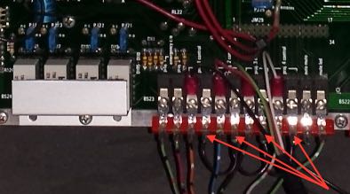
The lit "Go" led is to signify that a particular projector is the active projector. Some ignore it since the "Activate This Fader" led is also lit on the active projector, except when it is muted. I always connect it. There is no magic there. If you, as a temporary experiment, connect the "special" terminal to the "E" terminal on the CAT204, the Go LED will light (to prove to you how it works). So, what you want to do is run that "special" terminal to the projector relays on the back of the CP200 (there are four of them on the back of the Control unit). To the right of those relays are the terminals with two terminals per relay. The relays are dry contact so you have to wire up a ground (E) for each projector you have. I merely bring a convenient "E" terminal over and daisy-chain it to each relay and then land the "special" terminal from each remote to the other terminal from the appropriate remote.

The arrows in the picture above show the black wire I used to daisy chain the "E" to each relay.
| IP: Logged
|
|
|
|
|
|
|
|
|
|
|
|
All times are Central (GMT -6:00)
|
|
Powered by Infopop Corporation
UBB.classicTM
6.3.1.2
The Film-Tech Forums are designed for various members related to the cinema industry to express their opinions, viewpoints and testimonials on various products, services and events based upon speculation, personal knowledge and factual information through use, therefore all views represented here allow no liability upon the publishers of this web site and the owners of said views assume no liability for any ill will resulting from these postings. The posts made here are for educational as well as entertainment purposes and as such anyone viewing this portion of the website must accept these views as statements of the author of that opinion
and agrees to release the authors from any and all liability.
|

 Home
Home
 Products
 Store
Store
 Forum
Forum
 Warehouse
 Contact Us


 Printer-friendly view of this topic


![[Confused]](confused.gif) also the switch on the 517 is off but there is another jumper on that board labeled FADER BP with the choice of OUT or IN (currently OUT)
also the switch on the 517 is off but there is another jumper on that board labeled FADER BP with the choice of OUT or IN (currently OUT)


