|
|
 
|
|
Author
|
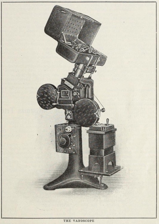
Topic: Vanoscope
|
|
|
|
|
|
|
Mitchell Dvoskin
Phenomenal Film Handler

Posts: 1869
From: West Milford, NJ, USA
Registered: Jan 2001
|
 posted 11-04-2015 03:47 PM


There is a lot of info on the internet about the Vanoscope company's bankruptcy and related fraud lawsuits, but not much about the actual projector. From what I have been able to find, I don't think that the projector ever got past the prototype phase.
From what I gather, it replaced the shutter with rotating mirrors, similar to how 8mm/16mm viewers work.
Patent Documentation
quote:
UNITED STATES PATENT OFFICE.
LEWIS C. VAN RIPER, OF NEW YORK, N. Y., ASSIGNOR TO VA'NOSCOPE- COMPANY, A CORPORATION OF DELAWARE.
MOTION-PICTURE MACHINE.
To all whom it may concern Be it known that I, LEWIS C. VAN RIPER, of the borough of Manhattan, city, county, and State of New York, have invented certain new and useful Improvements in M0- tion-Picture Machines, of which the following is a specification.
My invention relates to a projecting machine for motion pictures of the type in which the film is given a continuous travel, instead of the usual intermittent travel, and a plurality of mirrors are provided which reflect the images from successive pictures and tilt as they pass through the rays of light from the film to compensate for the movement of the film so that the projections on the screen remain stationary and each successive image is dissolved into the preceding one.
One of the principal objects of the invention is to provide a simple, accurately operating mechanism for accomplishing the necessary movements of the mirrors.
Another object of my invention is to pre vent vibration and dark intervals between successive pictures by keeping the volume of light constant and thus overcoming flicker.
A further object is to provide a mechanism in which the film travels over an arcuate path, the center of curvature of which lies in the axis on which the mirrors tilt so that as the distance of any given point on the film, while passing through the beam of light, to the rocking axis of the mirrors al ways remains the same, the image is not distorted and. a constant focus is maintained with respect to the lens and screen.
The invention has for further objects to provide such other new and improved constructions, devices and arrangements in projecting apparatus for moving pictures as will be hereinafter described and claimed.
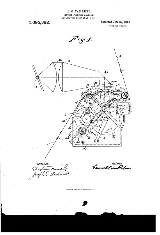
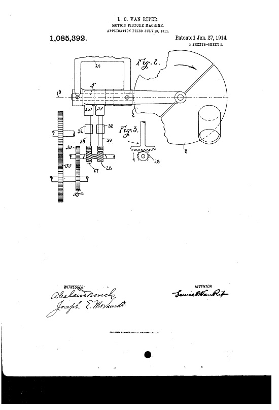
The invention is illustrated, in a preferred embodiment, in the accompanying drawings, in which Figure 1 is a side elevation of a projecting machine; Fig. 2, a fragmentary view of the mirrors and the apparatus for operating the same taken from a plane parallel to the mirrors; Fig. 3, a detail view of a part of the mechanism for rocking the mir rors; Fig. 4, a View of the parts shown in Specification of Letters Patent.
Application filed July 19, 1911.
Patented Jan. 21, 1914-.
Serial No. 639,356.
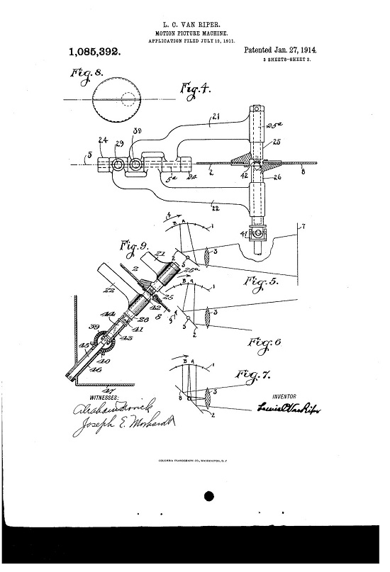
Fig. 2 looking edgewise at the mirrors which are in section; Figs. 5, 6, 7 and 8, diagrams illustrating the operation of the mirrors, and F 9, an elevation, with parts in section, of a portion of the mechanism for rotating the mirrors.
Like characters of reference designate like parts in the several figures of the drawings.
Referring to the drawings, 17 indicates the source of light, 18, 19 the condensers, 20 a stationary mirror, and 3, 3, the projecting lenses.
The film is continuously driven in the direction indicated by the arrows 11 by the sprockets 12 rotated by the crank handle 13 through the interposition of gears let, 15 and 16. in passing through the beam of light the film takes a curved path as shown in Figs. 1, 5, 6 and 7.
The images projected from the film are reflected through the lenses 3, 3, by the mirrors 2 and 8 and thence to screen 7 (Fig. 5). The mirror 2 is fixed to a shaft 25 having a reduced portion 25 revolubly mounted in a rocking bracket 21. The mirror 8 is simi larly secured to a shaft 26 revolubly mounted in the rocking bracket 22, the brackets being mounted on a shaft 5 the axis of which is indicated by the broken line 5 which is fixed in the bracket 2%. The brackets are rocked so as to give a forward tilt to their respective mirrors by the mutilated gears 27, 28, which mesh with sector gears 29, 30 on the rocking brackets 22 and 21, respectively, the mutilated gears being driven from gear 15 by gears 33, 33 and 3 1. The rocking brackets are returned to their initial position by means of cams 31 which operate against rollers 232 on the ends of rods 32, one of which is connected to each of the brackets. The cams are driven from crank 13 by gears and 36.
The mirrors are rotated simultaneously by driving the shafts 25, 26 which are connected by a universal joint 41:2. Connected to the shaft 26 by a universal joint all is a flexible extensible shaft consisting of a sleeve 1-8 which is formed with a bore square in cross section, a square shaft 1 1 slidable in said bore and connected with the universal joint -11, a shaft 45 mounted in a bearing 16 in the casing 47 of the machine, and a universal joint connecting the sleeve 43 with shaft 15. The flexible shaft is driven from the crank 13 by gears 1e, 37, 3S and miter gear 39 which meshes with miter gear tO in the shaft element Q5.
The operation of the machine above described will be best understood by reference to Figs. 5 to 8, inclusive. The mechanism is timed, let us suppose, so that as picture A on the film comes into the beam of light the image therefrom is reflected by mirror 2 which is inclined backwardly at its extreme limit. its the film moves forward, in the direction indicated by arrow 4:, the mirror tilts toward the position shown in Fig. 6 at such an angular velocity that the projection on the screen remains stationary. At the same time both mirrors are rotating and as mirror 2 is about to leave the field mirror 8 is brought into position to reflect the image from picture 13 upon the same area of the screen occupied by the reflected projection from picture A. The position of the mirrors at this time is shown by Figs. 7 and 8, C indicating bundles of rays projected on the mirrors from pictures A and B. The adjacent. edges of the mirrors at this moment are in parallelism since the axis 5 on which the mirrors tilt passes through the center of rotation of the mirrors so that at the time the edges of both mirrors are at right angles to the film no shadow is thrown as would be the case if the inner edges of the mirrors at this time stood at an angle to each other. It will be observed that by causing the film while passing through the beam of light to take a path which is the arc of a circle, the center of which is in the axis of tilting of the mirrors, each of the pictures being projected remains at a constant distance from. the axis on which the mirrors tilt so that there is no distortion of the image or change in focal distance with respect to the lens, as would be the case if the path of the film were straight.
While I have described my invention in a preferred embodiment, it is realized that modifications in the constructions, devices and arrangements shown might be made without departure from the principles of the invention.
lVhat I claim is:
1. An apparatus of the character described comprising means for guiding a picture film, means for continuously moving said. film, a plurality of reflecting devices each mounted 011 a rotatable shaft connected together by a universal joint, means for rotating said shafts, and means for shifting the axial relation of the shafts to each other.
2. An apparatus of the character described comprising means for guiding a picture film over an arcuate path, means for continuously moving a picture film, a plurality of reflecting devices each mounted on a rotatable shaft, a flexible or universal joint connecting said shafts, means for rotating one of said shafts, and means for changing the axial relation of said shafts to each other.
3. In a projecting apparatushaving means for continuously moving a picture film, means for guiding said film along an areaate path through a beam of light, a plurality of reflectors to receive and reflect the picture rays, means for rotating said reflectors, and means for rocking said reflectors upon a common fixed axis at right angles to and intersecting the axis of rotation, to cause the image of one picture to dissolve into the next.
4-. In a projecting apparatus the combina tion of a plurality of reflectors to receive and reflect the picture rays, means for rotating said reflectors, means for rocking said reflectors upon a fixed axis at right angles to the axis of rotation, means for continuously moving a picture film through a beam of light, means for guiding said film along an arcuate path substantially concentric with the rocking axis of said reliectors and synchronously with the rocking of said reflectors, to keep the distance between the film and the rocking axis of each reflector constant while moving through said beam of light.
5. In a projecting apparatus having means for continuously moving a picture film through a beam of light, a plurality of shafts connected together by a universal joint, a reflector attached to each of said shafts to receive and reflect the picture rays, means for rotating said shafts and reflectors, and means for supporting and moving said shafts in predetermined angular positions to each other synchronously with the movement of said film to rock said reflectors and compensate for the movement of said film.
(3. In a projecting apparatus having means for continuously moving a picture film through a beam of light, a plurality of shafts connected together by a universal joint, a reflector attached to each of said shafts to receive and reflect the picture rays, means for rotating said shafts with their reflectors, and means for supporting and moving said shafts and reflectors in predetermined angular positions to each other and at right angles to the axis of rotation to compensate for the movement of said film.
7. In a projectin apparatus having means for guiding a picture film along an arcuate path through a beam of light, means for moving said film, two mirrors continuously rotatable together to receive and reflect the picture rays, each mirror mounted on a shaft supported by an independent bracket, both brackets mounted on a common supporting shaft the axis of which is at right angles to the axes of said first mentioned shafts, and means for rocking each of said brackets with its shaft and reflector independent of the other to compensate for the movement of said film.
8. In a projecting apparatus having means for continuously moving a picture film, means for guiding said film along an arcuate path through a beam of light, a plurality of rotating reflectors, and means for rocking said reflectors upon an axis which passes through the center of curvature of the path of said film.
9. In a projecting apparatus having means for continuously moving a picture film, means for guiding said film over an arc of a circle through a beam of light, a plurality of reflectors continuously rotatable together to receive and reflect the picture rays, means for rocking said reflectors upon a fixed axis to compensate for the movement of said film, said rocking axis being concentric with the path of the are over which the film is moved.
10. In a projecting apparatus having means for continuously moving a picture film, means for guiding said film along and over an arcuate path through a beam of light, a plurality of reflectors to receive and reflect the picture rays, means for rotating said reflectors, and means for rocking said reflectors upon a common axis at right angles to and intersecting the axis of rotation, to cause the image of one picture to dissolve into the next.
11. In a projecting apparatus, the combination of a plurality of reflectors to receive and reflect the picture rays, means for rotating said reflectors and means for rocking said reflectors upon a common axis at right angles to the axis of rotation, means for continuously moving a picture film, means for guiding said film arcuately and concentric with the rocking axis of said reflectors to keep the distance from each portion of the film constant to the rocking axis of said reflectors while said film is moving through the beam of light.
12. In a projecting apparatus having means for continuously moving a picture film, means for guiding said film over an arched opening and through a beam of light, a plurality of reflectors to receive and reflect the picture rays, means for rotating said reflectors, and means for rocking said reflectors upon a common axis concentric with the radius of the curvature of said arched opening to keep the distance between the rocking axis of said reflectors and all portions of said film while passing through the beam of light constant to cause the image of one picture to fade into the next.
13. In a motion picture projecting machine, the combination with means for imparting a continuous travel to a film, of a plurality of mirrors supported upon shafts connected together by a universal joint, said shafts supported upon independent rocking arms, means for separately rocking said shafts, and means for rotating the mirrors simultaneously comprising a shaft connected to one of said mirrors and mechanism for rotating said shatt.
14. In a motion picture projecting machine, the combination with means for pro ducing a beam of light, of means for giving a continuous travel to a motion picture film through the beam of light, a plurality of rotary tilting mirrors arranged to reflect the images projected from said film, means for rotating said mirrors, means for tilting said mirrors and means for guiding the portion of the film in the beam of light so that it has an arcuate path with its center in the axis of tilting of the mirrors.
15. In a motion picture projecting machine, the combination with means tor producing a beam of light, of means for giving a continuous travel to a motion picture film through the beam of light, a plurality of rotary tilting mirrors having adj acently arranged edges, mechanism ior rotating said mirrors, and mechanism for independently tilting said mirrors so timed that the said adjacent edges thereof are in parallelism when at a given point while passing through the beam of light to cause the image of one picture to fade into the next.
16. In a projecting apparatus, the combination of means for continuously moving a picture film, a plurality of reflecting devices mounted 011 rotatable shafts, said shafts connected together by a universal joint, means for rotating said shafts and means for shifting the axial relation of said shafts to each other.
17. I11 a projecting apparatus having means for continuously moving a picture film through a beam 01' light, a plurality of rotatable reflectors to receive and reflect the picture rays, means for rotating said reflectors and means for rocking said reflec tors upon a common fixed axis at right angles to and intersecting the axis of rotation.
18. In a projecting apparatus having means for moving a picture film through a beam of light, means for guiding said film over an arcuate path through said beam of light, a plurality oi reflectors adapted to interchangeably move through said light beam to receive and reflect the light rays, means for moving said reflectors and means for rocking each reflector to continuously change its angular position with respect to the film while moving through said beam of light.
19. In a projecting apparatus having means for continuously moving a picture film through a beam of light, means for guiding said film over an arcuate path through said light beam, a plurality of rereflectors adapted to interchangeably move through said light beam between said film 15 and lens, to receive and reflect the light rays, means for moving said reflectors, and means for rocking each reflector to continu ously change its angular position with respect to the film While moving through said 20 beam of light.
| IP: Logged
|
|
|
|
|
|
Martin McCaffery
Film God

Posts: 2481
From: Montgomery, AL
Registered: Jun 99
|
posted 11-04-2015 06:16 PM

Here's the story from The Motion Picture News. Transcription errors are mine:
quote:
Motion Picture News December 6 1913
THE MOTION PICTURE NEWS
CONCERNING THE VANOSCOPE
By W. F. Herzberg. Director of the International Research Company
Editor's NoteSo much has been said and written about the Vanoscope optical projector, some affirming and some denying the possibility of optical projection by reflection, that The Motion Picture News some time ago authorized the International Research Company to undertake a thorough investigation of the machine and make a report of their findings on the facts for the benefit of our readers. The standing and authority of the International Research Company in the world of science and commerce alike is such that The Motion Picture News submits this refrain to its readers without further comment.
The Motion Picture News,
220 West Forty-second Street
New York City.
Gentlemen:
In compliance with your request of some months since, we have made an exhaustive investigation of motion picture machines manufactured and offfered for sale at the present day and at this time beg to submit a summary report which is but a synopsis of the great mass of detail which has been collected in the course of our investigation.
Our findings in the above can he summarised under A few general headings, viz.:
Mechanical Principles
The mechanical principles used in projecting a series of pictures intermittently at a speed of approximately sixteen per second, are, in all types of machines on the market today, dependent upon what is known in machines as the "Geneva movement" (in Cinematography termed the "intermittent movement"). This movement, variously adapted in connection with a revolving sector or series-of sectors (termed "the shutter" or "shutters") is the basis of all existing motion picture machines.
In short, the film, on which is imprinted the series of pictures, is drawn across a standard aperture in the path of the light rays from an optical lantern: each picture stopping momentariiy before this aperture by reason of the film having imparted to it a "start" and "stop" motion by means of the Geneva movement. During the travel period of the film the sector or shutter cuts off the light rays from the aperture, thus eliminating the film movement on the screen.
To realize the ideal in this principle of projection each picture should be projected for the longest possible period and-the changing Inuit line picture to another should occupy the shortest possible period of time. When these conditions are fully met the result would be a brilliant picture without "flicker" (a term used in the art to denote the dark period produced by the sector cutting off the rays of light during the interval in which the change from one picture to another is made). Therefore these two functions in conjunction with an optical lantern, condenser system and projecting lens, variously assembled, constitute what is termed "the machine" and is either hand o motor driven.
The Vanoscope's Construction
With the great volume of data before us, which our complete research into every phase of cinematography produced, we proceeded to investigate the Vanoscope, both as to its mechanical construction, soundness of optical principles involved, it's adaptability for the purpose intended wherein it meets the requirements lacking in projecting machines of the period, and its possibilities on the market.
We herewith summarize our conclusions and findings under a few general headings Both the large commercial Machine and what is termed the "Junior" or"Home" Vanoscope were carefully inspected part for part and a careful study of the duty required of each part and its fitness both as to performance and durability.
The general design has been well thought out and the parts of ample section to ensure rigidity in operation and perform with the least motive effort the function for which they are designed. The machine assembled as a whole consumes a surprisingly small amount of space in comparison with other machines of similar purpose.
The mechanical and optical principles involved in the consruction and operation of the machine are absolutely foreign to any machine manufactured today, which precludes the possibility of paying royalty to a patent company in which the patents covering the essential features of present-day motion picture machines are pooled and for the use of any one or more of these patents the manufacturer pays royalty to the holding company. This feature alone represents a saving in manufacture figuring into thousands of dollars per annum.
Principles and Operation
First - As the machine operates without the usual shutter there is absolutely no interruption or diminution of the light projected through the film onto the screen. The elimination of the shutter precludes all possibility of flicker and the eye-strain resultant therefrom.
Second The Vanoscope operates without an intermittent movement, therefore there is not present the jar and noise which is usual where non-reciprocal movements are in use. The absence of these in a machine eliminates the usual mechanical tremor which is transmitted to the screen in a magnified state and is evidenced by a blurring of the picture.
Third As the film in the Vanoscope travels in a continuous, unbroken motion, the wear and breakage of the film are reduced to a minimum, thereby greatly lessening the cost of same and also the annoying stoppage and interruptions which at present exist by reason of the film being subjected at all times to the sudden strain and pull of an intermittent movement. A continuous moving film is a feature absolutely new.
FourthIn view of the fact that all parts arc continuously running. greatly reducing the friction in the machine, thereby consuming less energy to operate.
FifthAs the projection of the arc is not brought to a focus on the film. it is possible to stop the film at any point without fear of ignition. This
is a feature that is absolutely new and could not be accomplished on any other machine.
SixthIn the Vanoscope the picture does not move off the screen from top to bottom, but one picture is dissolved into the other directly, thus always insuring a full picture on the screen 100 per cent of the time. Travel ghost cannot exist, as it does not become necessary to move the pictures off the screen at a speed of 16 per second or greater in order to maintain the persistence of vision. The Vanoscope projects pictures at eight per second and even slower without any visual perception of change from one picture to another This feature insures an initial saving in the length of the films of 50 per cent and over, which in turn effects a saving in material, labor, bulk and transportation almost beyond estimate.
SeventhThe Vanoscope projects pictures with distinctly stereoscopic effect. This result is evidently obtained by the dissolving principle, by which one picture is dissolved into its succeeding picture, and projected through a common source of light. The pictures on the screen have great depth and stereoscopic roundness and completes the illusion of the existence of the object projected, which seems to be actually seen rather than pictured. When the Vanoscope projects one, two or three pictures per second it is impossible to see the change from one picture to the other because of this dissolving effect, and the more slowly the pictures are projected the more evident is this remarkable stereoscopic principle demonstrated.
The Market for the Vanoscope
Leaving out entirely the use of projecting machines for amusement purposes, there remains a vast untouched field in commercial and educational use. The use of the machine of to-day in these fields is at a standstill by reason of its being inadequate to meet the requirements demanded for these purposes. As the Vanoscope removes all the objections above tabulated and entails improvements and economies not as yet broached, we have no hesitancy in saying that in gauging the period of improvement in projecting machines of the past that the Vanoscope is about 20 years ahead of the times.
Our full report, including all data collected and results of tests, is now in course of preparation and will be submitted as soon as it can be properly tabulated and reduced to writing
Respectfully submitted,
The International Research Co.Page n637
| IP: Logged
|
|
Martin McCaffery
Film God
Posts: 2481
From: Montgomery, AL
Registered: Jun 99
|
posted 11-04-2015 11:24 PM
Well, I think we can see what happened to the Vanoscope:
quote:
Motion Picture News April 25, 1915
ROBINSON AWARDED $189,000 VERDICT IN VANOSCOPE SUIT
WILLIAM J. ROBINSON has won a verdict of $189,765.70 in Judge Charles M. Hough's branch of the United States District Court in his $1,000,000 breach of contract suit against Lewis C. Van Riper and the Vanoscope Company. The jury in the case was out two hours hearing the testimony adduced by the plaintiff's attorneys, Hector M. Hitchings and Irving E. Burdick, to show that their client had entered into an agreement with Van Riper on January 13, 1913, whereby he was to have the exclusive right to sell the stock of the Vanoscope Company for six years.
Before he was able to create a demand for the stock, he said, he had to spend about $35.000 in the perfection of the machine.
When the machine had been improved, he said, Van Riper, who held the patent rights, abrogated the contract and gave the exclusive right to sell the stock to Harris Hammond, son of John Hays Hammond, and John Hobbs. The company, according to Robinson, got $50,000 for transferring the stock selling rights. In another suit, concluded less than a month ago in the United States District Court before Judge Hunt, Robinson sued Van Riper for personal damages and was awarded a verdict for $100,000.
Robinson will move for an attachment of the Vanoscope Company's property in case the judgment is not paid.
Mr. Robinson stated to a representative of "Motion Picture News" that he would immediately begin the manufacture of Vanoscope machines and within a reasonable time begin to fill many contracts now pending with exhibitors. The machines will in all cases be leased only, as the contracts specify, not sold outright.
| IP: Logged
|
|
|
|
|
|
All times are Central (GMT -6:00)
|
|
Powered by Infopop Corporation
UBB.classicTM
6.3.1.2
The Film-Tech Forums are designed for various members related to the cinema industry to express their opinions, viewpoints and testimonials on various products, services and events based upon speculation, personal knowledge and factual information through use, therefore all views represented here allow no liability upon the publishers of this web site and the owners of said views assume no liability for any ill will resulting from these postings. The posts made here are for educational as well as entertainment purposes and as such anyone viewing this portion of the website must accept these views as statements of the author of that opinion
and agrees to release the authors from any and all liability.
|

 Home
Home


![[Wink]](wink.gif)


 Printer-friendly view of this topic