Christie P35GP Projector Tips
The following tips are a collaberation from our own testing as well as reader's input specifically for the Christie P-35GP projectors.
Although we have tested everything herein and found the following tips
to be of excellent advice, these tips are not endorsed by Christie Inc.
and are provided for your assistance "at your own risk".
PLEASE NOTE: There are many images on this page.
Should they not all download properly, hit your reload button.
Aligning the Lateral Guide rollers
This adjustment will stop the left to right weaving during projection.
Check the alignment of the two lateral guide rollers (#19, see figure 1 below). Ideally the outboard (soundtrack) "stationary" guide roller should be as close as possible to the outboard gate rail. Both guide rollers should be adjusted identically in the following fashion. Note: if your gate and trap was not aligned in this manner prior to the cutting of the aperture plates, this will result in your pictures being off center through the aperture. If there is any doubt whatsoever, contact your engineer before proceeding.
Loosen the two set screws (#24, figure 1) one to two full turns.
This will allow you to adjust the lateral guide roller back and fourth
with the two point screws (#17, figure 1) so that the outboard lateral
guide roller is as close as possible (but still free spinning) to the outboard
gate rail when the gate and trap are closed together. Warning:
do NOT unscrew the two point screws (#17, figure 1) more than two full
turns as doing so will cause the jewels (#23, figure 1) to fall out!
Once you have aligned the outboard guide roller in this manner, lock it
down with it's set screw (#24, figure 1). Now tighten the inboard
point screw (#17, figure 1) until the lateral guide roller can no longer
spin with the gate and trap open. From this point, loosen the point
screw ever so slightly until the lateral guide roller just becomes free...and
no more! Lock this position down with the inboard set screw (#24,
figure 1). Repeat for the second lateral guide roller.
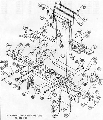
Figure 1
Check the Turret Latch
This adjustment will help to minimize the horizontal blurring of the image, particularly in scope (2.35x1) format.
On the newer models with turrets, there is no actual "latch" but an assembly very similar to a pad roller on most projectors. If you close your turret and find there is a little bit of play in the closed position, it can generally be remedied by tightening the allen head screw on the underside of the latch. Note: there is such a thing on Christie equipment as "too tight". If this adjustment is overtightened, the turret will close hard on the allen stop screw and then bounce 1/16 inch back out. Should this happen, loosen the latch screw slightly.
While we're on the subject of overtightening, if a lens will only focus
in one direction on a Christie turret, loosen the two mounting bolts on
the lens barrel. Overtightening will seize the focusing assembly.
If your lens will not sit tightly in the barrel, place a small strip of
masking tape on the barrel of the lens to simulate a slightly larger lens
barrel.
Tweeking the Lens Alignment
This adjustment will ensure the aperture is properly aligned up with the masking and screen.
Now that you've fine tuned the lateral guide rollers, you must go back and check the alignment of the lenses. Thread up a loop of PA35 (RP40) target film and project on screen.
First, above the lens in use is an eccentric adjustment. Loosen this and adjust the image on screen horizontally until centered, then retighten.
Second, on older models, you will need to remove the side cover plate
whereas on newer models there will be two plastic plugs to remove to gain
access to the stop adjustments. Insert a 5/32 allen wrench into the
upper hole for the flat stop and into the lower hole for the scope stop.
This adjustment will center the image vertically. Always make sure
to cycle the turret between formats after making an adjustment to ensure
you have this precisely aligned, as the Christie turrets are notorious
for not staying seated at the end stop.
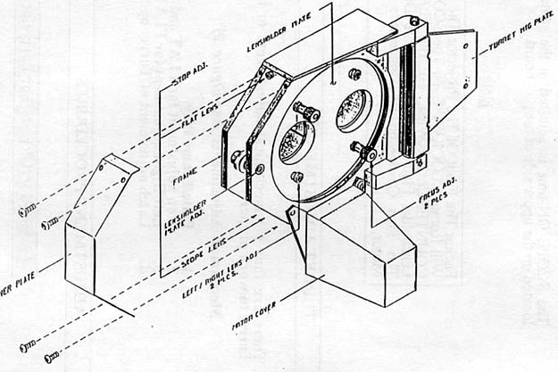
Figure 2
Modifying the Gate Tension
This adjustment will help prevent the spring blade from breaking in half and provide, in most instances, a more stable picture. This is particularly useful with FilmGuarded prints, as they are very slick from the lubrication.
Before you do anything here, where is your gate tension knob normally set? If you run at 1 or 2, skip this step. If you run at 4 or 5, proceed.
First, order a second "spring blade" Christie part #120679-001 (#4, figure 3) for each projector you will be modifying. Once you have this part, remove the trap from the projector and unscrew the bottom two allen bolts holding the gate bands in place (#34, figure 1).
Once these are free, unscrew the two allen screws holding the gate tensioning
assembly in place (#38, figure 1). The gate tensioning assembly and
bands should easily pull outward from the back side of the trap.
Take special note of the placement of the spring blade as you are removing
the trap (see figure 3).
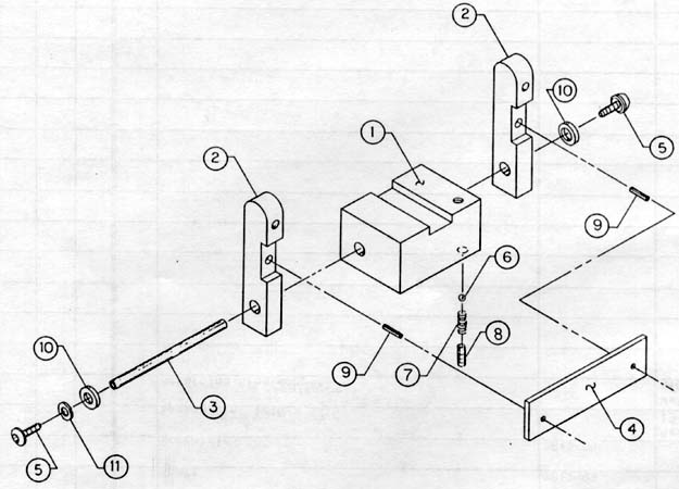
Figure 3
Now, place the original spring blade as well as the new spring blade sandwiched together and reinstall the gate tensioning assembly. Then, reattach the two gate bands to the bottom edge of the trap and reinstall the trap assembly in the projector.
A current gate tension setting of 1 is now roughly equal to a previous gate tension setting of 4. Running the projector above 3 will cause this part to become soft from the heat of the lamp and snap. With two of these parts installed, the gate tension setting can be left at 1 and there will be no stress on the part.
Note: older/worn gate bands will provide superior performance
than brand new bands. Unless yours for some unknown reason gets bent,
stick with the ones you have. They will outperform new ones straight
from Christie Inc.
Fine Tuning the Gate For Projection Angle
This adjustment will assist in correcting focus for steep projection angles.
There is not a lot of variable on a Christie projector to correct for steep downward or upward projection angle. However, if your projector has a focusing field horizontally across the image where it is in focus and adjustment of the focus knob raises or lowers that field, try this trick.
On the back side of the trap, loosen the two securing screws for the
catch plate (#25, figure 1) and position it as far as possible away from
the gate bands. Run your PA35 test loop. If the focus got worse,
repeat the above positioning the catch plate as close as possible to the
gate bands. This is pretty much all the play these machines will
give you and this tiny adjustment will make a little improvement, but not
a lot in overall focus.
Modifying the Blowers in the Lamphouse
This modification will help stabilize the projected image.
What you say? What does the lamphouse have to do with the steadiness of the projector? EVERYTHING! Believe it or not, these blowers can actually shake the hell out of the projector...blurring the projected image. It doesn't take much dirt or the balance weight to be off just a hair to cause this.
There are two ways to handle this. First you can junk the blowers you have and purchase new ones. Second, you can insert a bloser "cushion" to protect the lamphouse from shaking. Since most theaters will choose the latter, here's how to do it...
***TURN ALL POWER OFF TO THE CONSOLE BEFORE PROCEEDING***
There is an intake blower and an exhaust blower. The intake blower
is the one demonstrated here. The exhaust blower can be cushioned
in the same manner.
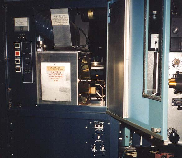
First, remove the access panels and open the doors of the console.
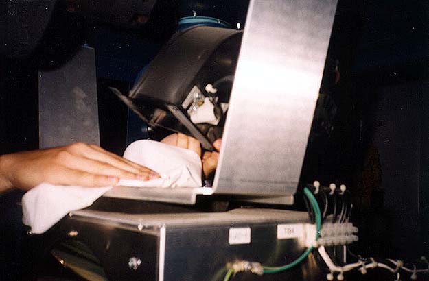
Remove the intake blower (on top of the reflector) by unscrewing the
four mounting screws. Once the blower is free, wipe the area clean.
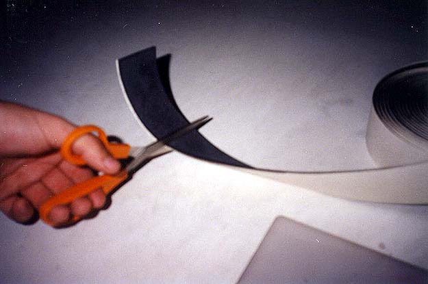
Once removed, you will need to make four strips out of foam insulation
tape. This tape is readily available at hardware stores and is ideal
as it comes with adhesive on one surface. Another cushioning material
that works quite well is a mouse pad, although some mouse pads may be too
thick for this purpose. Two strips should be cut to 4 1/4 inches
long and the other two strips should be cut to 3 inches long. Ideally
the width should be between 3/4 to 1 inch wide for all four strips.
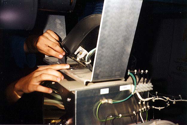
Place the four cushioning strips between the mounting holes so there
is no air leakage and the mounting holes are not blocked. The inside
edges should be relatively flush with the opening on top of the reflector.
This need not be perfect.
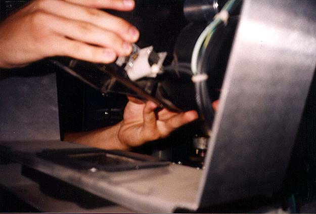
Remount the intake blower fan loosely. Now, the trick here is
to tighten the four screws enough to slightly compress the cushioning material,
but NOT so much that the screws are tight and the cushioning material is
fully compressed. You are now done and the shaking of the blower
will be absorbed by the cushioning material and will not be transferred
to the image on screen.
Adjusting The Dower To Open Fully On It's Own
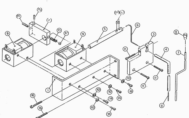
Take the back cover off of the projector. Locate the douser solenoids as shown in the explosion diagram above. Tighten the #14 screw in one turn increments until the douser will swing fully up on it's own. Note: nothing needs to be disassembled to perform this adjustment.
Changing The Belts
Following are the three diagrams for belt paths.
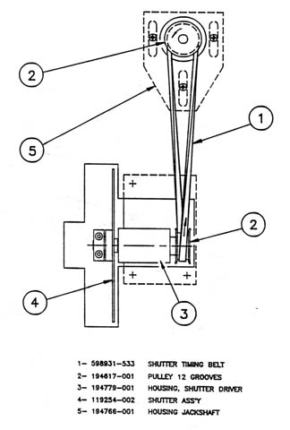
SHUTTER TIMING BELT
Christie part #598931-533
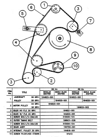
OUTER TIMING BELT
Christie part #598931-528
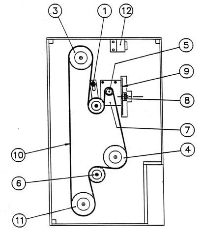
INNER TIMING BELT
Christie part #598931-179
Note: #1 tension pully MUST be pulled as close to #5 idler assembly to prevent jumping of the belt teeth during advance by hand.
Typically this belt must be fairly tight while the other two should be as loose as possible without bouncing.
All belts should be replaced once a year and checked for wear every 3 months.
Panef belt dressing applied to the belts will greatly reduce the shedding and premature wear.
Every 6 months, the belts should be removed and a tiny flat head screwdriver used in between each tooth of all pulleys, to remove the buildup from the belts.
Threading the P35-GP Projector
Many, many, many prints get destroyed on Christie projectors. Although the design could've been modified so such a risk isn't quite as high, the problem is in the threading of the loops.
The following is a scan direct from the projector manual.
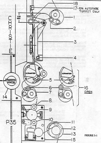
Why have we reprinted the threading diagram? First because few
operators bother actually reading them. Second, someone in their
infinite wisdom came up with the idea to make a "two finger" loop during
training. Many booth trainers have been using this method of instruction
ever since. This is a bad idea, as no two people's "two fingers"
are the same size.
In reference to the Christie projector, the lower loop MUST be extremely small. Notice the #16 diagram off to the right of the lower loop. After the projector is threaded, open the lower sprocket pad roller as shown and turn the projector motor over by hand. If threaded properly, the film should pull snug and tug ever so slightly on this pad roller (at the smallest point of the loop during operation). If this machine is threaded more than one loop over this amount, polyestar film will slap up and down so hard that the film will hit up against the bottom of the Ultramittent, causing green horizontal dash scratches. (If anyone at Christie is reading this, here is your tip on creating guard rails on the underside of the Ultramittents.)
Now the upper loop is fairly forgiving. However, for the steadiest picture, the loop should be as big as possible WITHOUT the film bowing outward towards the screen between the top of the gate bands and the top of the gate itself. You can check this by turning the motor by hand and stopping at the upper loop's largest point (right before the next pulldown of the Ultramittent). We recommend a piece of masking tape be placed on the back wall of the projector marking the "high" and "low" points of the loop in it's ideal setting. This will also assist in ensuring any digital penthouse readers are exactly in sync with the picture.
Notice the tension on the optical sound head. If your sound drum
bearings are in excellent condition, you may thread in this manner.
Unfortunately, we find this to be rare on these projectors and the film
must be tightened about one sprocket hole from what is shown in the above
diagram to prevent "wow and flutter" in the reproduction of the sound.
Ideally, there should be no excess slack, but with only the slightest amount
of actual tension spreading the two sound head lateral guide arms apart.
THE OPERATOR